Hi
I would like to introduce you to my project of a small mITX PC case “PuZZle”. The case is designed for the mITX motherboard platform and has 2x FAN input, 1x FAN output, and 1x input from the PSU.
It is designed for air cooling and small 120mm water cooling. Large 240 compact cooling will not fit, so watch out!!!
The project is designed so that the individual parts can be printed separately even on smaller areas of 220x220mm. Prusa MK4 / S or BambuLab A1 can handle it without any problems. On a larger printing area, say 350x350mm, it is possible to print the entire set of parts as a whole without division.
Why “PuZZle”?
Each part of the cabinet, for example “MB plate project mini pc”, consists of several parts marked V1-V4 and after printing and gluing they form a whole (plate). Each part has teeth on the side where the glue is applied, so-called “PuZZle”, which then connect the opposite similar part “PuZZle”, but you probably know that everyone who has ever built a puzzle 🙂
all parts glued together into one whole see picture, this is the visible inside,
below a small video of the correct gluing.
Assembly
The entire cabinet is largely glued, while other parts are joined with screws or magnets.
When gluing joints, be careful not to let the glue seep onto the visible side of the part. You can prevent this by adding paper masking tape to the joint on the visible side. See video or image.
For gluing, use medium viscosity or gel adhesives. Do not use thin adhesives as they may seep onto the visible side!!!
It is good to use an activator for each joint.
Visible Side
The side of the part that is to be visible, such as the outer cladding, should be pressed facing the opposite way (first contact layer)…..but you probably already know that 🙂
The visible sides also include the insides where the PC components are stored.
See image.
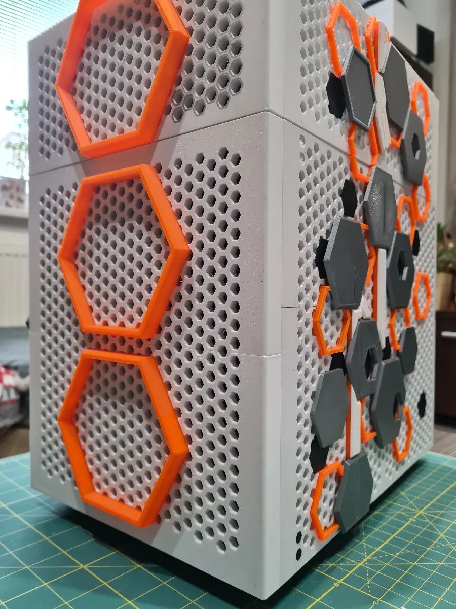
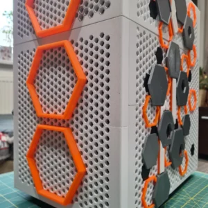
Outer Covers and Accessories
As seen in the images, the outer covers have accessories glued on that protrude from the cover.
This is a separate set of parts for printing and is optional.
It does not have to be part of the cover, and it is up to you whether to add it. It will not affect the functionality of the part.
The outer covers themselves can be painted individually; for printing, it is recommended to use materials with similar properties. When painting, do not combine PLA with PETG or others. It is always necessary to maintain the same material: PETG+PETG or PLA+PLA.
See image of accessories on the cover.
Corect supplement orientation
On the back of the accessories are numbers indicating the correct position of the accessory and then small dots that show the orientation. Just store them according to the picture, turn them, and stick them. For some, a second layer of accessories is then applied (see the pictures).
Screwing Together
Completely glued plates, for example (back plate, MB plate, front plate, down plate, up base, top plate) are joined with screws M3x12, M3x10, or M3x8.
See the picture.
In some holes, it is necessary to use threaded inserts M3x5.7 to ensure the connection holds. Otherwise, it is sufficient to simply insert the screw into the hole and tighten it. The thread will be cut into the plastic.
Neodymium Magnets
The outer covers can be removed except for (top front cover, top left cover, and top cover). They are held from the inside by neodymium magnets 10x3mm. For some parts, it is necessary to print magnet holders.
See the picture and their orientation.
LED Strip
If you decide to illuminate the case, the LED strip needs to be cut into individual parts and soldered. The LED strip holder is used for properly sticking the LED strip and subsequently inserting it into the part.
This step is optional and does not have to be part of the case; it is up to you.
See the picture.
Filament
For this project, Prusament PETG Orange Transparent, Prusament PLA Galaxy Black, BambuLab PLA Black, BambuLab PLA Silver, Devil Design PETG White, and 3D Jack PETG Black filaments were used.
For basic prototyping, where I used trial and error 🙂 to test individual parts, I used Spectrum PETG White Arctic, Devil Design PLA White, Devil Design PETG Dark Red, and Devil Design Brown.
The internal parts are printed from PETG, the outer covers from PETG, and the accessories from PLA and PETG. All parts were printed on a Prusa MK4 printer. If you have a boxed CORE XY printer, nothing prevents you from using more durable materials.
Settings
For PLA or PETG, no complicated settings are necessary. You should use a bed with a textured surface and always spray a little 3D adhesive or something similar.
PETG 240 nozzle, bed 80
PLA 230 nozzle, bed 60
support no, top base support yes
infill 15%, the file “project mini pc MB board” has an infill of 40% at the edges
What is not included in the files
-LED strip
-plexiglass window
-front filter (fan dust cover), front fan cover is included
Material build
Use screws (more and more 🙂 with a flat head, preferably with an internal hex.
M3x12 screws…45x flat head with internal hex (maybe more 🙂
M3x10…..14x – flat head with internal hex (otherwise, there is a risk of collision with the PSU) !!!!
M3x8…….20x – external cylindrical head with internal hex
M3x5.7 threaded inserts……buy a whole pack
M3x6 standoff screws ……4x
medium viscosity glue
glue activator
neodymium magnets……10x3mm….50x, 6x3mm….16x
flexible tip for the screwdriver (back cover montage)
Assembly procedure
mini PC project (base for motherboard)
back plate (one FAN hole)
front plate (two FAN hole)
bottom plate (mark down plate)
upper base (mark top, up base)
upper interlayer (mark top, up, or inplate)
upper cover (mark top cover)
The upper cover and the upper plate are connected by magnets; first, it is necessary to screw the upper plate to the upper base, then insert the magnets, and then insert the upper cover. The edge of the upper cover protrudes slightly; this is not an error
The back plate, mini pc project, and front plate are connected by screws on the back side of the plate (mini pc project). There are 4 square legs with holes for screws and in the upper part, holes for magnets… see pictures.
All 3 parts (back plate, mini pc project, front plate) are inserted into the bottom plate into the holes for the teeth; the bottom plate is then connected by screws from below.
Do not glue the plates together; only glue the joints on the individual plates.
The upper base is attached with screws from above and then from the inside (4x square legs of the mini pc project plate).
Use threaded inserts for all holes; insert them carefully, do not press on the soldering tip.
Each hole for the threaded insert has a diameter of 3mm; adjust the diameter of the hole according to the size of the threaded insert.
Stand-off screws 4x are inserted directly into the plastic without a threaded insert.
All covers (external) hold magnets; connect two magnets and then insert them, do not put them together with the same polarity, they hold firmly in the plastic; if they fall out, just a drop of glue under the magnet.
If you decide to use LED strips, use an LED strip holder, glue the strip, solder the individual parts of the LED strip, and insert them into the rear holes (grooves) on the covers… see pictures.
Contacts for the LED strip are provided by a magnet holder with two pins for contacts; the place of gluing is not fixed, it is your choice.
The choice of cables is up to you, just a diameter of 0.5mm.
The magnet holder for covers is attached with a screw into the threaded insert.
Magnet holder loop 2 during the installation of water cooling should be attached before adding the cooler.
Each part that you will glue together, first try to attach it; if they do not have any unevenness, then glue it, always use paper adhesive tape… see video.
The hole for the main switch has a diameter of 19mm; for a larger hole, use a negative volume modifier when printing.
The transparent side window is plexiglass from Perspex; it is cast acrylic, do not use extruded acrylic because it sticks and is difficult to process.
Do not use a heat gun or a tanning gun for large areas; the plastic could warp, use isopropanol and wipes for cleaning.
For experiments when printing, use cheap filament that is sufficiently dried.
upper base
back plate
back plate+ mini pc projekt plate + front plate
square legs with holes for screws and in the upper part, holes for magnets.
upper view
bottom plate
back side IN/OUT MB
SSD and M.2 SSD holder and cover (inside)
front hole for FAN and thread insert M3x5,7
dust cover and holder
stand off screw for MB
screws for bottom plate 12mm
And my assistant 🙂
my pc configuration
-ROG Strix B760-I Gaming Wifi
-Intel mCore i7-12700K
-Samsung 1TB 990 Pro m2
-Ram Corsair 32GB DDR5 Vengance 6000MHz
-Asus GeForce RTX 4060Ti
-DeeoCool LS320 water cooler
-3x Corsair LS120 FAN RGB
-PSU Gigabyte 750W UD Gold
If there is any problem with the files, please write in the comments and I will add them.
Good luck :::. Good printing :::::.

Reviews
There are no reviews yet.